 |
ECE671 - DSP in Embedded Systems
|
  Team Members Bhegin Ntagazwa Maurice Farah Professor
|
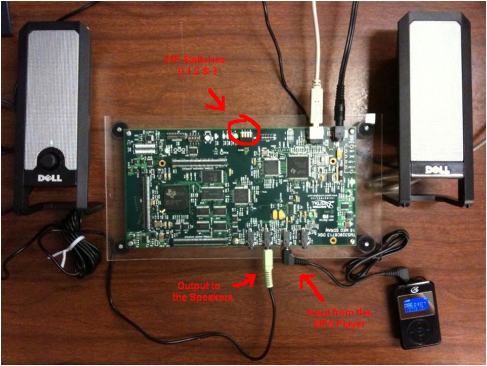
ProceduresThis project started by design of FIR using Matlab tool fdatool as used in lab projects. Refer to example 4.4 from the text book (“Digital signal processing and applications with C6713 and C6714 DSK” by Rulph Chassaing) and inputting the data shown on the text book. The internet search to obtain starting filter frequency boundaries for audio mixer yielded Low Pass 300Hz, Band pass (LP to HP), and High pass using Frequency cutoff of 5000Hz. Once all the data are input in the fdatool and processed. Matlab generates a data file which is loaded in DSP tool and processed in conjunction with the C code. The C code design combined functions of delay.c, echo.c, and FIR filter sited as text example 4.4. Also integrated some runtime controls such as several parameter controls via GEL extensions and use of the four switches and LEDS to select run mode shown on board below.
Figure 4: Project Hardware
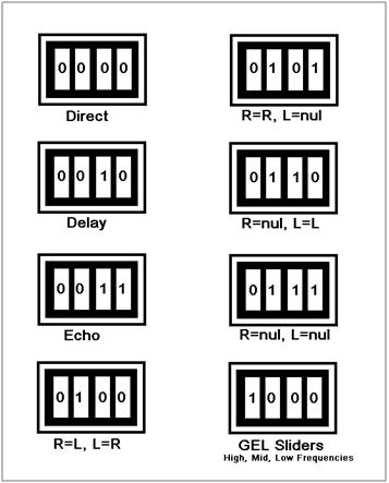
Figure 5: Switches Combination This is where you can see the window tool is used to generate the signal.
The window tool which has it mathematics calculation defined on section 4.6 of the text book helps to transform the rectangular
window function w(n)=1 for |n|=Q and 0 for |n| = anything else.
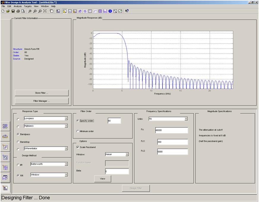
Figure 6: Matlab tool fdatool generating bandpass signal frequency (F) at 300 to 5000 Hz. (hbp350t5kf48)
|
|
© 2011 Copyright Maurice Farah. All rights reserved. |