 |
ECE671 - DSP in Embedded Systems
|
  Team Members Bhegin Ntagazwa Maurice Farah Professor
|
This project combines the implementation of (six) finite impulse response (FIR) filters, delay line, and echo effect subprojects using DSP tool TMS320C6713 DSK. The FIR filters are tools used to provide three groups of frequency components per channel where the gain adjustment gave control to amount of each frequency group was present in output. IntroductionThis project demonstrates channel routing among left and right, signal delay, echo, muting select channels, or application of Low pass, Band pass, and High pass filters to signal provided Line input and output Lineout/Head phones on TMS320C6713 DSK. The use of FIR filters requires two MatLab modules to produce the filter COF files. The fdatool function offers the type of filter and design parameters related to chosen filter. Exporting the resulting array variable in MatLab where the dsk_fir67.m program formats the output to a COF file. The COF files are the coefficients used to implement the FIR filter.
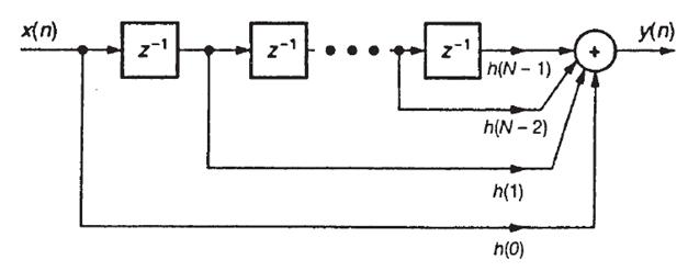
Figure 1: FIR filter structure showing delays The input signal to the TI DSK 6713 board is sampled in the AIC23 module. The AIC23 was an ADC section and a DAC section. The DSP reads a unsigned integer 32 (Unit32) value of A/D via the McBsp providing the value present at line input jack. The DSP writes a Uint32 to AIC23 where it contains values for left and right channels. The DSP is designed to do the FIR math very fast, allowing real-time computations to live signals to line input.
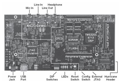
Figure 2: DSK TMS320C6713 circuit board
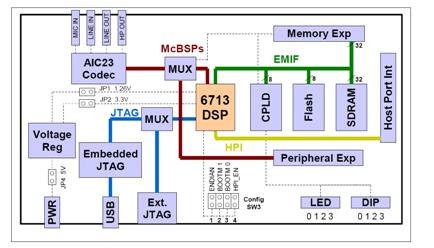
Figure 3: Block diagram of DSK TMS320C6713 The DSK–board device used in this project comes with a wide variety of
application environments. Key features include:
|
|
© 2011 Copyright Maurice Farah. All rights reserved. |