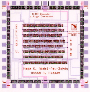
1995, "Residue to Mixed-Radix Decoder and sign Detector," For efficient
arithmetic computations RNS are proposed. This design accepts the three
residue digits of the moduli set (64, 63, 31) and decodes them to their
equivalent MR digits. Each residue or MR digit is expressed in 6 digits.
The design accepts a clock and reset as iput signals to pipeline the system.
The design is also capable of decoding the sign of the input residue number.
If the most significant bit of the most significant MR digit is "0", then
the sign of the input of the input RN is positive, otherwise it is negative.
Twenty input pins are used for reset, clock, and the residue input digits.
Twelve pins represent the most significant two-output MR digits.
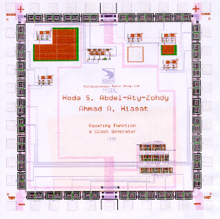
1995, "Squaring Function, Median circuit, and clock Generator," This
chip includes three projects: (1) An efficient squaring function combinational
logic design that accepts an input operand of 7 digits and outputs the
squared value. The output is expressed in 14 bits. However, since the LSB
of the output matches that of the input , and the next LSB of the output
is expected to be 0 irrespective of the input. Therefore, only 12 output
bits are used. The algorithm used is based on the Viterbi approach where
the approximation error is viewed as an additional noise and the
Viterbi algorithm can compensate for any inaccuracies. (2) Five, simple,
reliable, astable multivibrator clock generators capable of producing sharp
waveforms with low duty cycle, and wide frequency range of choice (from
0.6 Hz up to 10 KHz). These are suitable for sensors and actuators interface
applications. (3) An analog 3 input median circuit is also included in
the CMOS n-well tiny chip (2.22*2.25)m2.
1995, "Self-Organizing Feature Mapping NN,"
1995, "ASIC for Color Space Conversion," This tiny chip contain the
design and VLSI implementation of an ASIC, which performs conversion, in
real time, of the R, G, and B color coordinates to CIE standard L* a* and
b* color coordinates. The high-speed operation of the ASIC is achieved
by pipelining the input data, then performing parallel operations. The
design occupies an area of 1.55*1.45 mm2. It is intended to
be used in colorimeters instrumentation for color measurement, and in color
machine vision systems. Inputs are 3 bits each color. Output are 7 bits
except l* which is 6 digits. Two control signal (RESET and CLOCK) are used.