ME 4300 Project
Winter 2020
Due Date: Monday April 20, 2020, 5 pm
The loading dock door of a small trucking and storage company faces a narrow alley between the trucking company and the building next door, severely restricting the size of the loads that the company can handle. They would like to install a chainfall above the alley, spanning the distance between the buildings, to allow them to load and unload heavy objects from their trucks. They intend to fabricate the supporting structure from an existing supply of low-grade steel tubes and would like the structure to be portable by two men, if possible.
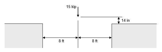
For this project, you are to design a 2-dimensional simple truss to support a 15,000-lb load over the center of a 16-ft span and 14-in higher than the tops of the buildings, as shown in the figure below. The truss cannot extend into the gap between the buildings and must rest on the horizontal surfaces shown. In order to be properly supported, the truss must be at least 1-ft wider than the space between the buildings. The vertical deflection of the point of application of the force must not exceed 0.20 inch.
For simplicity, you need not be concerned with the weight of the truss when analyzing the forces, but the total weight is important and should be as small as possible. Use round steel (UNS G10100 CD steel) tubes only from Table A-8 (included in the Quiz and Exam Resource, English units only) of the text and do not design the joint connections or the connections to the buildings. You must be concerned with buckling of the compression members. The factor of safety with respect to all forms of structural failure (yielding and buckling) must be at least 2.2.
Prior to manufacture and installation, a municipal engineer will inspect your report. For the report include:
- a dimensioned sketch (to scale) of your truss,
- a complete force analysis,
- a stress analysis for each member,
- buckling analyses for the compression members,
- specifications (sizes and lengths) of each member,
- your analysis of the deflection of the truss and
- the total weight of the truss.
Recall that a truss is an structure componsed entirely of straight, two-force members that are connected at their endpoints. Loads are applied to a truss only at the connections, or joints, and never between joints (therefore, a joint must be located at the point indicated above). Since each member is straight and two-force, it can only be in simple tension or compression.
Suggested strategy. To solve this design problem, consider the following steps in order:
- Start with an triangular truss and add two members at a time to keep it composed entirely of stable, triangluar portions.
- Solve for the forces in each member by the Method of Joints.
- Find the cross-section area in TA-8 for each member that will give it at least the required factor of safety. Once this is done for all the members, the truss passes the yielding criterion.
- Analyze the members in compression for buckling: find the critical slenderness ratio and, for each compression member find its slenderness ratio, determine if it is an Euler or Johnson column, calculate the critical load and the factor of safety. If all these factors of safety are at or above the required value, the truss passes the buckling criterion. Note: zero-force members can be used to effectively shorten a compression member and significantly increase its buckling load.
- Using the geometry from (1), the forces calculated in (2) and the areas determined in (3), calculate the vertical deflection of the point where the load is applied using Castigliano's Theorem. If this deflection is less than that required, it passes that criterion. If not, try increasing the areas of the members that are contributing the most to the deflection.
- Once you have a truss that passes all of the criteria above, you should seek to reduce its weight it through structural optimization. This involves redesigning the truss based on your observations of how the forces change when the positions and angles of the joints and members are changed. Often, trusses weigh less than 1%, or less, of the loads they support.
Use of design software
You are not required to do so, but you are free to use any type of software you wish to do this project, such as CAD, SolidWorks, Catia, Excel, etc, or even programs or scripts that you write yourself. The Excel file below is a small 2-dimensional truss FEA application - it is a reference; its use is not required. If you choose to use any software, you must verify that the results are correct. You will do this by selecting one compression member from the truss and calculating by hand its load, stress, yielding factor of safety and buckling factor of safety. In addition, you will also need to verify the vertical deflection of the point where the load is applied using Castigliano's Theorem. For the deflection calculation, you can use the member forces calculated by the software.
Excel resource - Truss Analysis
Reporting
Include only the following sections in your report:
- Abstract - three sentences max, must include the weight of your truss
- Discussion - a brief, illustrated, narrative describing your solution process and the evolution of your design, including a fully dimensioned sketch of your final truss
- Results - a single table containing all of the information in the first list above
- References - as always, cite any and all sources of information consulted and used in this assignment
- Appendix - hand calculations verifying the results from software, complete set of input data for software (screen shots are ok)
NOTE - This is an individual design project. For designs that satisfy all of the requirements, higher grades will be assigned to lighter trusses. You are competing with the other members of the class to develop the lightest truss that satisfies all of the requirements. Good luck.