|
School of Engineering and Computer Science ECE-576 LANE DETECTION AND TRACKING By PhIlipp Czeschka Christian Kobel Maher Youkhana
|

|
The TRDB_D5M module code was built in Verilog which is available on the CD from the Cam Kit. For our project this code had to be modified as necessary to incorporate the NIOS II into our project. The major entities of our project are the CCD_Capture entity, RAW2RGB entity, and I2C_CCD_Config entity. With these entities we can receive and translate the data from the cam. Furthermore the data will be stored to the SDRAM. The data can be read out and processed afterwards by the NIOS II. The following figures shown the major entities created by the RTL Viewer.
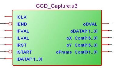
Figure 23: RTL Block Symbol of CCD_Capture
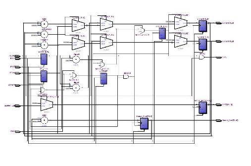
Figure 24: RTL Diagram of the CCD_Capture
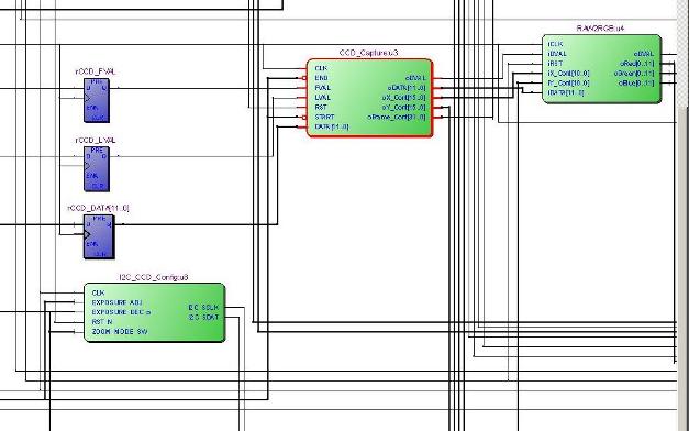
Figure 25: RTL Diagram of D5M Image Entities
The I2C_CCD_Config module is used to create and transmit the control signals from the DE2 board to the D5M board. The CCD_Capture module decodes the FVAL, LVAL, and data signals from the D5M card. This device utilizes a simple state machine that represents the possible values of the LVAL and FVAL signals. When the devices transitions to the state representing image data, the 12 bit image pixel data is captured and then sent to the RAW2RGB module which translates the 12 data into the corresponding Red, Green, and Blue data arrays. These values are then stored in SDRAM utilizing the X and Y coordinate value to function as the write address used in the SDRAM.
TRDB_LTM ModuleThe code for the panel is also available on the CD from the panel kit. Unfortunately there were some problems with the implementation of both kits at the same time. For that reason we did not implement the panel kit and we have not explained the module in this report. To display the picture the VGA output is used like in the example code for the cam kit.
MATLAB Image Processing CodeTo create the necessary code for our color tracking, MATLAB was used. After the code worked properly, a C-code was created by MATLAB.
Image Processing: The following abstract shows the main part of the image processing for the Lane detection. There are numerous techniques for vision-based lane detection, for example: Edge detection Color segmentation This processing focuses only on the color detection and shows the raw data without filtering. But already this method results a useful lane image. To have best performance a mixture of both methods and a filter leads to the best results. For testing issues the color of the lane is chosen by the mouse click on the picture. %% Get location of cursor & color of clicked pixel imshow(ImageA); hold on; drawnow; U_temp = get(gca,'currentpoint'); Point = round(U_temp(1,2:-1:1)) %[125; 85]; Note the order of the 2nd index is reversed. ImageA_Val = double(ImageA); DesColor(1:3) = ImageA_Val(Point(1),Point(2),:); …
The function Mask is scanning the image and plot a logic ‘1’ if the color is within the defined color range or a logic ‘0’ if not. After that the location of the pixels in the image will be highlighted by another color.
%% Find pixels of approximately the same color Mask = abs(ImageA_Val(:,:,1)-DesColor(1)) < Delta & ... abs(ImageA_Val(:,:,2)-DesColor(2)) < Delta & ... abs(ImageA_Val(:,:,3)-DesColor(3)) < Delta;
[Row, Col] = find(Mask); plot(Col,Row,'.','color',[0 1 1]); drawnow; …
The clicked location is highlighted by a circle. %% Plot a circle to show clicked location Angles = [0:0.3:6.28]; Circle = [W1*cos(Angles)+Point(2)*ones(1,length(Angles)); W1*sin(Angles)+Point(1)*ones(1,length(Angles))]; plot(Circle(1,:),Circle(2,:),'.y','markersize',5); drawnow;
Depending on the resolution of the camera the color of the same lane in every pixel is more or less different, hence it is important to define a delta range and allow a variation of the color.
%% Use GUI to pick a color % W1 defines the diameter of the marker for picked color % Delta defines the maximum deviation from the picked color
W1 = 15; Delta = 8; set(gcf,'windowbuttondownfcn','PickLocateShow_3','windowbuttonupfcn','')
Shown below is image before the image processing.
Figure 26: Picture before Color Tracking
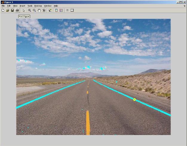
After the image processing in MATLAB the attempt to track the shoulder is shown below. The shoulder is tagged turquoise.
Figure 27: Color Tracking in MATLAB
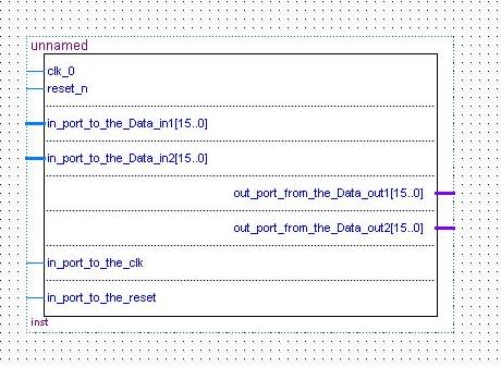
The next step is to convert the MATLAB code in C-code. MATLAB provides a special command to convert a m file to C-code. mcc –c myfile “command to convert m file in c-code” After converting, the C-code can be implemented in our NIOS II project. NIOS II Soft Core Processor ComponentsThe NIOS II soft core processor is added to the design as a block / symbol file. The block generated from the SOPC instance is depicted in the following figure.
The NIOS processor is used for our actually image processing. The majority of the functionality of this block is actually realized in the C code application that is downloaded to the chip once the hardware design is configured in the FPGA. At this point essentially functioning like a Microcontroller with a JTAG interface for downloading the compiled C code. The C-Code components include the module to read the memory, the color tracking processing algorithms and send data to the LCD. The C-Code four our color tracking processing is included in appendix B. |

|
School of Engineering and Computer Science ECE-576 LANE DETECTION AND TRACKING By PhIlipp Czeschka Christian Kobel Maher Youkhana
|